
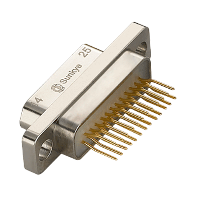
MIL-DTL-83513 Micro D Connectors
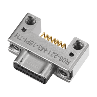
MIL-DTL-32139 Nano D Connectors
Discover more applications using Sunkye Connectors' solutions

The power connector is generally composed of plug and socket. The plug is also called free connector, and the socket is also called fixed connector. The connection and disconnection of the circuit is realized by the insertion and separation of the plug and socket, so various connection modes of plug and socket are produced, which is known by many operators. Here is an analysis of the attention points in use:
1. The termination
1) When the power connector is terminated, the termination and inspection shall be carried out in strict accordance with the corresponding termination specifications or requirements, and the power connector shall be terminated according to the corresponding contact number. The maximum thickness of the insulation layer between the selected cables and conductors should match the distance between contacts, and the cable core should match with the contact terminal. When crossing and merging wires between contacts, the diameter of the multi-strand cable core should be considered, and it is forbidden to cross or merge wires between the crimping holes of contacts;
2) During the welding, the electric soldering iron with corresponding power should be selected according to the diameter of the bare wire. The welding time of each contact is generally less than 5s. Pay attention to preventing the soldering flux from penetrating into the insulator, so as not to cause the decrease of product insulation resistance;
3) When cleaning the power connector (including the cleaning of the contact), a silk cloth dipped in absolute ethyl alcohol can be used after drying. It is not allowed to use acetone and other chemical solvents that have harmful effects on the power connector;
4) When the power connector is not in the insertion state, it is necessary to add the corresponding protective cover or take other dust-proof measures.
2. Check the power connector before the insertion
1) The model, code, number, insertion position and direction of the power connector shall meet the requirements of design and process documents;
2) The trial hood is not loose and the tied top does not fall off;
3)There is no bend on the cable bundle or conductor of the trail hood opening, and there is no damage on the outer skin;
4) There is no fracture of the shield grounding wire and no looseness of the soldering terminal that connects the shell;
5) The housing and the interface of the power connector shall be free from deformation, crack, thread wear, looseness or defect of fasteners and shedding of coatings;
6) The locking device shall be intact;
7) For the power connector with a sealing ring, the sealing ring shall be intact;
8) There shall be no redundancies at the interface (insulator surface and socket);
9) The pin and socket shall not be skewed or deformed;
10) The surface of the insulator at the pin root shall be free of broken, uplifted and fallen metal debris;
11) There should be no obvious retraction or protrusion of the pin and socket. Compared with the normal pin and socket on the same plane, the retraction or protrusion distance should not be greater than 0.5mm. Otherwise, it is necessary to check whether the pin or socket is properly assembled or retracted;
3. The insertion and extraction operation
1) Before inserting, it is necessary to confirm whether the code of the plug and socket to be inserted, the shape of the interface, the locating key and slot, the positioning color code, the locking staple bolt and neck as well as the positioning screw and screw hole are consistent and accurately positioned;
2) In the process of pushing or screwing in the power connector, align the plug with the butting surface of the socket and centralize the cable or wire, then gently push or slowly screw the lock sleeve into place along the axis direction and lock it tightly. If it is found that the two butting surfaces are skewed, the positioning is not accurate, the hand feeling is too tight to be beyond the normal force or there is obstruction and other abnormal feelings, the operation should be stopped, then pull out the power connector along the axis direction and carry out the status checkout. Insert the power connector again after trouble removal. It is allowed to use special auxiliary tools to insert and extract the power connector;
3) Do not rotate the cable or wire at the outlet of the trial hood when tightening the trial hood of the plug or socket;
4) During blind insertion, it is recommended to use lighting and devices with visual functions (such as micro cameras or endoscopes and monitors) to monitor the blind insertion process. When carrying out the blind insertion operation in empty-illumination and supervisory equipment conditions, the corresponding characteristics of the interface to be inserted should be felt clearly with fingers, then insert the power connector in place and lock it tightly;
5) In the locking operation, if it is found that it cannot be locked normally, the connector shall be pulled out and checked in time. Insert and lock the power connector in accordance with regulations after checking correctly;
6) For the power connector with thick and hard cables, the cables should be fixed to prevent the failure in unplugging and the damage of the power connector caused by cable droop;
7) After the power connector is inserted and locked, the cable at the trial hood outlet shall be kept in a natural extension state, and the initiation site of the bending shall generally be more than 30mm away from the trail hood outlet. Unless otherwise specified, the inner bending radius of the cable shall not be less than 4 times of the outer diameter of the cable;
8) When the power connector is plugged in and pulled out, it is not allowed to grasp the cable or wire outside the trail hood for operation.
4. The testing
1) The probe should meet the requirements when testing cables or electronic equipment. It is strictly forbidden to use probe or copper wire for direct detection, so as to prevent making the power connector jack big or damaging the inner wall or distorting the pin;
2) Before the insertion testing of the testing cable and the power connector on the electronic equipment, the power connector (plug and socket) on the testing cable shall be checked first. If there is any appearance damage, pin (hole) corrosion, pin distortion, jack deformation, dust pollution, wire breakage and shielding wire breakage, the insertion shall be stopped;
3) During the test, the plug-in operation of the power connector should be carried out after the power supply is disconnected for at least 3 min. Hot plugging is prohibited;
4) After the model and product electrical performance test is completed, the power connector shall be fused according to the requirements of the design and process documents if the power connector is not separated for a long time, and the locking device of the power connector shall not be loosened in the fusing process.
5. The storage
The power connector shall be stored in the environment where the temperature is -10~+40℃, the relative humidity is no more than 80% and there is no acid, alkali or other corrosive gases around.
Sunkye Connection Technologies provides a wide product portfolio with a complete interconnect solutions offering. Sunkye connectors and cables assemblies are complementary with Sunkye backshells and conduits.


 Aug 09, 2019
Development of Micro Connector
 Apr 04, 2020
The Material of the Connector
 Jul 15, 2020
Classification of Connectors
 May 04, 2020
Automotive Connectors
 May 31, 2019
Sunkye at Expo Electronica 2014, Moscow
 Nov 15, 2019
How To Make High-Quality Connector
 Jan 25, 2020
Four Types Of Industrial Electrical Connectors
 Nov 24, 2019
The Connector Applications Are Everywhere
 Sep 25, 2020
Related Knowledge of SMA RF Connector
 Oct 30, 2019
D Sub Connector Introduction
 Dec 01, 2021
Connectors' Revolution of 1000km off The Earth
 Apr 13, 2020
Why is a Poor Connector Prone to Fire?
 May 31, 2019
SUNKYE will Release Type C Project on October
 Apr 25, 2020
The Second Generation Circular Military Connector
 Jun 24, 2020
Application of Military Electrical Connectors (3)
 Apr 07, 2020
Market Status of Miniature Connectors
 Oct 19, 2021
Subsea Connector needs a new revolution
 Sep 21, 2021
Connection Mode and Purchase of Aerospace Connector
 Feb 15, 2021
The Power Capacity of RF Coaxial Connectors
 May 13, 2020
Reliability of Aerospace Electrical Connectors (2)
 Jan 04, 2021
The Structure and Material of Connectors
 Nov 17, 2022
Robotic Arm Works 7*24 in Manufacturing
 Mar 20, 2020
Connector Quality Test Type
 Jul 12, 2020
Introduction to the Connector
 Nov 01, 2021
Meet Sunkye at SEDEC 2020 Fair!
 Nov 23, 2022
Hermetic Connectors for Implantable Medical Devices
 Nov 06, 2019
Connector Classification
 Dec 22, 2020
The Transient Interruption Detection of Connectors
 Oct 20, 2020
The Failure Mechanism of Connectors
 Feb 25, 2020
How to Choose the Right Medical Connector
 Jun 27, 2020
Crimping and Welding of Military Connectors
 Jul 30, 2019
Market Status of Micro Connectors
 Nov 03, 2019
Some Solutions For Poor Terminal Pressing
 Mar 08, 2020
Sunkye: Safety, Innovation, Reliability
 Sep 20, 2019
Strictness of Military/Aerospace Specifications
 Oct 18, 2022
Hermetic Connectors for Implantable Medical Devices
 Jan 13, 2020
Overall Performance Parameters Of Connector
 Jan 03, 2024
Connector — A Big Player in Your Supply Chain
 Aug 02, 2020
Electrical Performance of Connector
 May 31, 2019
Sunkye Super Pin Connector
 Nov 01, 2019
Five Common Features of USB Connector
 Mar 29, 2020
Demand for Heavy Truck Connectors Increases
 Sep 08, 2022
How Does Environment Temperature Affect Connectors?
 Apr 22, 2020
Production Process of Connector Contacts
 Feb 10, 2020
The Function And Prospect Of Medical Connector
 Sep 12, 2019
Reliable Connectors Are the Secret of UAV Success
 Jan 04, 2023
Four Connection Methods of Circular Connectors
 Dec 29, 2019
Material Of Automotive Connectors
 Jul 09, 2020
The Importance of Connectors in Medical Equipment
 Sep 08, 2019
What are Avionics Connectors?
 Feb 13, 2020
Connection Between Brain And Machine
 Jan 19, 2020
Brief Introduction Of Flat Cable Connector
 Jan 01, 2020
Development Trend Of Automobile Connector In China
 Nov 09, 2019
Introduction To Connector Knowledge
 Jan 31, 2020
The Development Of D-sub Connectors
 Jul 03, 2020
Manual Assembly of Connectors (1)
 Feb 07, 2020
The Rapidly Growing Market For Medical Connectors
 Oct 13, 2020
Various Coaxial Connectors
 Jan 22, 2020
Differences Between Connector And Terminal
 Nov 12, 2019
Production Technology of Connector
 Jan 18, 2021
Knowledge of FPC Connectors
 Nov 02, 2021
MEET SUNKYE AT SAHA EXPO 2021 FAIR!
 Nov 04, 2019
How Military Connectors Work
 Nov 03, 2020
The Guide for Selecting Electrical Connectors
 Apr 01, 2020
Connectors for Special Applications
 Jun 21, 2020
Application of Military Electrical Connectors (2)
 Oct 02, 2023
MEET SUNKYE AT ADIPEC 2023 FAIR
 Aug 09, 2021
What Are High Density Connectors?
 Dec 02, 2019
Basic Structural Member Of Connector
 May 31, 2019
Sunkye Type C 10Gbps Test on April
 Oct 07, 2020
How to Distinguish FFC Connector and FPC Connector
 Nov 10, 2019
The Future Trend Of Automobile Connector
 Oct 31, 2019
The Introduction Of SMT
 Oct 06, 2020
Description of Pogo Pin Connectors
 Feb 19, 2020
Reliability of Aerospace Electrical Connectors
 Jul 08, 2021
Structural Analysis of Aerospace Connector
 Dec 11, 2019
The Main Classification Of Crimp Connection
 Aug 07, 2019
A Revolution in Connector Technology
 Oct 13, 2020
Selection Factors of RF Connectors
 Sep 19, 2020
The Necessity of Waterproof Connectors
 Jul 06, 2020
Manual Assembly of Connectors (2)
 Jan 25, 2021
The Analysis of Connector Electroplating Problems
 Nov 10, 2020
The Manufacturing Process of Electronic Connectors
 Nov 11, 2019
Brief Introduction Of Automobile Connector
 Nov 17, 2020
Selection Factors for SMA Connectors
 Jun 06, 2019
Alloy 52 UNS N14052 Material Report
 May 27, 2021
The Importance of Connectors in Electrical Equipment
 Sep 04, 2019
Market Profile of Micro PCB Connectors
 Nov 14, 2019
How To Choose The Right Connector
 Sep 02, 2019
Four Processes of Producing Connectors
 Oct 01, 2020
Structure and Material of Waterproof Connector
 Dec 08, 2020
Some Knowledge about RJ45 Connector
 Sep 28, 2021
Correct Use and Safety of Avionics Connectors
 Nov 29, 2019
Importance Of Connectors
 Oct 10, 2019
Types and Advantages of D-sub Connectors
 Apr 28, 2020
How to Detect Medical Connectors
 Dec 08, 2019
Connection Methods Of The Connector
 May 31, 2019
TWIST PIN: THE LIGHTSPOT OF SUNKYE
 Nov 05, 2019
Wearable Connectors Tend to be Miniaturization
 Dec 17, 2019
Interconnection Level Of Connector
 Jun 25, 2019
Sunkye Super Pin Datasheet
 Aug 02, 2021
Introduction to Vehicle Connectors
 Nov 17, 2023
Future Development Trends of Circular Connectors
 May 31, 2019
Everything You Need to Know: Type C
 Jun 15, 2020
7 Tips for Connector Design (2)
 Nov 08, 2019
Miniaturization Development Technology Of Connector
 Dec 26, 2019
How To Classify Industrial Connectors
 Jul 17, 2020
Sunkye Market Matrix
 Sep 28, 2019
Development Trend of Miniature Connectors Technology
 Oct 13, 2023
Several Design Ideas for Electronic Connectors
 Jan 16, 2020
Brief Introduction Of Strip Connector
 Sep 14, 2019
Miniaturization Trend of Mil Connectors
 Aug 15, 2023
Extreme Conditions Bring up Hermetic Connectors
 Sep 18, 2019
Definition of Mil Standard Connector
 Oct 06, 2019
How Military Spec Connectors Work
 Aug 01, 2022
Connectors Make Sensors Work Well on Equipment
 Sep 24, 2019
Notes for Welding D Type Connector
 Jan 07, 2020
The Performance Of Automobile Connector
 Jun 12, 2020
7 Tips for Connector Design (1)
 Sep 26, 2019
Market Status of Micro Miniature Connectors
 Sep 13, 2020
Fusion of Connectors and Sensors
 Jul 18, 2020
The Basic Structure of the Connector
 Jan 28, 2020
The Connector Industry Is Booming
 Jan 11, 2021
How to Select Connectors for Hardware Design
 May 10, 2020
Reliability of Aerospace Electrical Connectors (1)
 Dec 14, 2019
Naming Of Connectors
 Dec 23, 2019
Technical Principles Of Connectors
 Jun 18, 2020
Application of Military Electrical Connectors (1)
 May 31, 2019
Features of Type C
 Dec 05, 2019
Disassembly Tools For Automotive Connectors
 May 31, 2019
Sunkye Will Postpone the Release of USB 3.1 Type C
 Sep 06, 2019
Polytetrafluoroethylene-PTFE
 Nov 10, 2020
Applications and Characteristics of BNC Connectors
 Jul 21, 2020
What is a Military Specification Circular Connector?
 Jun 01, 2021
Functions and Advantages of Electrical Connectors
 Aug 03, 2019
Connector D Type
 Dec 01, 2020
How to Improve the Reliability of RF Connectors
GET IN TOUCH
MIL-DTL-32139 Nano D Connectors
 English
  日本語
日本語  한국어
한국어  français
  Deutsch
  Español
  italiano
  русский
  Türkçe
  Svenska
  Nederland
