1. Introduction
The reliability of RF connectors is a very important problem in the whole machine or the system use, because as a component, the reliability of the RF connector directly affects or determines the reliability of the whole machine or the system. The reliability of RF connectors is related to their structural design, production process, production technology, selected materials, quality control and their correct application. The structural design is the most important among these factors, which plays a decisive role in the inherent reliability of the product. Therefore, in every stage of development and design or in the reliability growth test, special attention should be paid to how to improve and ensure the inherent reliability and the use reliability of the product.
With the passage of time and the continuous development of science and technology, the design theory and measurement technology are constantly updated and improved through the test of practice and the accumulation of experience, and the defects and limitations in the early designs are gradually exposed. Therefore, it is necessary to adopt new concepts, new technologies and new materials to improve the old products and old structures, and take measures to improve the inherent reliability of products.
In order to improve the inherent reliability of RF connectors, it is necessary to follow the basic design principles and characteristics of RF connectors and take measures to improve them without reducing their electrical characteristics or ensuring that their electrical characteristics are not affected. The failure forms of RF connectors are as varied as those of all connectors, but the main common failure form is the contact failure of the contacts. Aiming at the contact failure forms exposed in the development, test and application of RF connectors, some improvement measures should be taken to get certain effects. In terms of structural design and application of auxiliary agents, the measures are summarized as follows: reinforcement method, calibration method, balance method, coating lubrication method, optimum seeking method, etc.
2. Measures
2.1 Reinforcement method
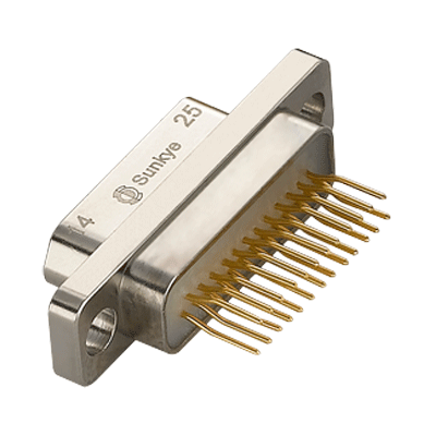
Aiming at the outer conductor of the RF connector or the parts of the inner conductor where contact failure is prone to occur, the reinforcement method is to add stiffeners and cut no grooves or narrow grooves to improve the rigidity and mechanical strength of the failure parts and improve their contact reliability and mechanical life without affecting the electrical characteristics (e.g., VSWR, insertion loss) of RF connectors.
Case 1: In the vibration test and the mechanical life test of the Q9 RF connector( an obsoleted type) and the early BNC RF connector, the distortion and flying flake phenomenon often occur at the elastic grooves of the outer conductor end face, which results in the increase of the contact resistance of the outer conductor and the failure. Aiming at this type of failure, reinforcement measures should be taken, that is, reinforcement bars should be added at the end of the connectors such as the BNC RF connectors specified in the current IEC168-8 standard.
In order to verify the effect before and after the reinforcement of the two different outer conductor structures, four pieces of Q9-J5 and four pieces of Q9-KY5 processed according to THE SJ 500-83 standard, four pieces of BNC-J5 and four pieces of BNC-KY5 processed according to the IEC169-8 standard, as well as four pieces of BNC-J5 and four pieces of BNC-KY5 processed according to the IEC169-8 standard are respectively inserted and extracted at 8-10 times per minute by the same group of personnel when other conditions are the same. Test the contact resistance of the inner and outer conductors once for every 100 times of inserting and extracting, and insert and extract them for 2000 times in total.
According to the test results, the inner conductor structure designs of the two products are similar, and the change of contact resistance is also similar with the increase of the insertion and extraction time. The contact resistance of the two products doesn’t change much, which can meet the requirements of ministry standard and IEC standard, and there is a large margin. The contact resistance of the outer conductors of the two products varies greatly with the increase of the insertion and extraction time. Take the Q9 FR connector for example, if the insertion and extraction frequency is in 500 times, the contact resistance is greater than 2.5 mΩ; if the insertion and extraction frequency is in 1000 times, the contact resistance is less than 8 mΩ, which is in line with the ministry standard but does not accord with the standard of ICE; for BNC connectors, the contact resistance is less than 2.5 mΩ within 500 times of insertion and extraction, and the contact resistance is still less than 8 mΩ within 1000 to 2000 times of insertion and extraction. It can be seen that the product reliability is obviously improved after the adoption of reinforcement.
Case 2: In the structural design of RF connectors, the inner conductor jack is usually designed in the shown structural form. In the process of using micro-miniature RF connectors, jack damage, collapse, fragment and other phenomena will occur in the structure, resulting in the contact failure. With the reinforcement method and under the condition of satisfying the electrical characteristics, the connector is designed into a structural form, which can greatly reduce the contact failure caused by the damage of jack and improve the reliability of the product.
2.2 Calibration method
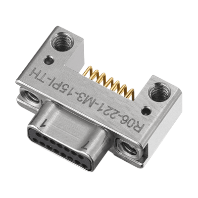
Calibration or alignment method is to shorten the insertion length of pins and extend the axial length of threads in the interface structure design of some micro RF connectors. During the connection process of connectors, this method can make the connector plug contact with the socket first, and alignment the pin and the jack in a straight line before contacting and connecting, so as to prevent the pin from damaging the jack in the connection process, resulting in the failure.
For example, the jack damage shown in Figure 7 is prone to occur in the connection process of SMA connector and APC-3.5 connector. After using the calibration method, the failure caused by the jack damage can be effectively avoided in the connection process of the connectors such as 2.92mm, K, and 1.85mm connectors.
2.3 Balance method
The balance method refers to the structure design of high frequency contacts in high and low frequency hybrid connectors. The adoption of the balance method should meet the requirements of electrical characteristics (such as RVSW) within the applicable frequency range and consider the overall mechanical life of high and low frequency hybrid connectors. The jacks of the inner conductor system should be strengthened and the inherent reliability of high-frequency contacts should be improved as much as possible.
The outer conductor diameter of high frequency contacts is small in high and low frequency hybrid connectors, so the jack of the conductor system is easily to be damaged in the connection process if the structure is designed according to the nominal impedance of 50Ω or 75Ω. However, in high and low frequency hybrid connectors, the requirement for the applicable frequency range of high frequency contacts is be very low. In this way, the high frequency characteristic can be eliminated, the outer diameter of the jack can be increased, and the mechanical strength can be improved, so the reliability of the whole connector can be improved.
For example, the inner diameter of the outer conductor of a high frequency connector can be φ3.1 mm. If the impedance is designed by 50Ω, the inner diameter of the conductor is φ0.94 mm, and its cut-off frequency is about 34 GHZ, but the product use frequency is less than 50 MHz; if the jack is designed by φ0.94 mm, the mechanical strength is very poor, and the failure phenomenon caused by the broken jack often occurs. The adoption of the balance method eliminates the high frequency performance and increases the outer diameter of the jack. The jack with the designed outer diameter of φ1.4mm ensures that the VSWR is less than or equal to 1.2 in the 0-0.5GHz frequency range, which meets the use requirements, greatly improves the jack strength and improves the use reliability.
2.4 Coating lubrication method
The coating lubrication method means applying the coating agent or lubricant on the surface of the contact parts of RF connectors to improve the corrosion resistance and wear resistance of the contact parts, so as to improve the contact reliability and mechanical life.
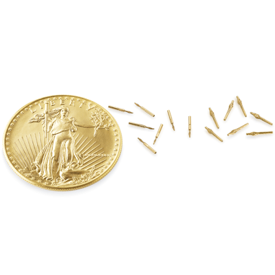
Gold is the most difficult to corrode and tin is the easiest to corrode according to the degree of electrochemical corrosion of gold, silver and tin, but it is quite the opposite that the gold-plated contact is corroded most, while the tin coating is corroded less from the actual use of electroplating contacts. This is because as a precious metal, gold tends to be thin, while tin, as a base metal, is thicker. In the case of general plating quality, the relation curve between the thickness of the coating and the number of pinholes is shown in Figure 9. Thin coatings with more pinholes are easy to be corroded; thick coatings are difficult to be corroded.
In order to prevent the contact failure caused by the corrosion of the thin gold-plated layer on the contact, coating agents or lubricants will be applied on the contact surface to reduce the number of pinholes and improve corrosion resistance and abrasion resistance, so as to improve the contact reliability.
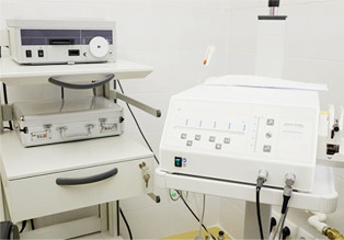
In order to verify the coating effect, the same parts with and without coating agents are placed under the atmosphere of SO2, H2S and HNO3 for contrast test at high temperature.
As is shown in the figure, the connectors are all affected by corrosive gas, but the effects on the correlation difference between coated and non-coated connectors are wide. The contact resistance without the application of coating agents increases greatly, and the effect of SO2 is particularly significant. After applying coating agents, the increase of contact resistance is significantly inhibited, and the total contact resistance is within 10 mΩ. It can be seen that applying coating agents on the surface of the gold-plated connector is very effective to improve its corrosion resistance.
In addition to improving the corrosion resistance, applying lubricants to the contact coating surface can also improve the insertion and extraction performance and abrasion resistance, thus improving the mechanical life of the product.
The commonly used coating agents and lubricants are: oil electric contact surface lubrication protectants YJ-9201, YX-9202 and DB-823; grease electric contact surface lubrication protectant Z-9203; wax electrical contact surface lubrication protectants LJ-9204, LY-9205 and LX-9206; paraffin wax (CNH2N+2). The Japanese brands are C2000, C9050, C5500, C9312, C9300, etc.
2.5 Optimum seeking method
The optimum seeking method refers to choosing the suitable connection mechanism optimally according to use characteristics in the design of the connection mechanism of RF connectors or in the selection of connectors to avoid the contact failure caused by the improper selection of the connection mechanism, so as to improve the use reliability.
The common connecting mechanisms of RF connectors are shown in Table 1. Different connecting mechanisms have different applicable conditions and characteristics, so the applicable connecting mechanism should be selected according to the characteristics of use.
3. Conclusion
Some of the measures and examples listed above have been reflected in the standard interface structures of the products, and in some cases, the two structures coexist in the same product type. As measures to enhance the inherent reliability of products, the methods listed above are not only or unique. Designers can carry out specific analysis according to the contact failure forms occurring in product contacts and adopt methods that are different from the above measures to improve the use reliability. They can also apply one or some of the above measures jointly to improve the use reliability. It is unnecessary to change the structure when the existing structure can meet the use requirements.
The methods above aim at different failure forms, and they can be used as a reference for designers to design products initially. In addition, the methods can be clues in analyzing connector failures and searching for failure causes, and they can also be adopted in reliability growth tests.
 English
  日本語
日本語  한국어
한국어  français
  Deutsch
  Español
  italiano
  русский
  Türkçe
  Svenska
  Nederland